usage of position and perpendicularity tolerances for holes
Drawing
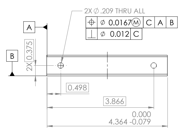
M3-5 Tolerances in Inches
Bilateral: +0.008/-0
True Position: 0.0167 @ MMC
Perpendicularity: 0.012
Bilateral Tolerance
We use nominal X.00 mm screw sizes
We dimension our clearance holes for X.30 mm
We actually use X.50 mm drill bits
This gives us 0.20 mm = 0.008 inches of tolerance
True Position
Assuming we use X.30 mm as our clearance hole and we have a reference plane at y = 0
We don't want our holes to be misaligned. We use a clearance tolerance of 0.30 mm. Our position tolerance is a 0.3 diameter circle; this means if one hole is at y = 3.0 and one is at y = 3.30, our holes won't be mis-aligned. Our upper bound for the y=3 hole will be 3.15 and the lower bound for the y=3.30 hole will be 3.15. This gives us a true position tolerance of sqrt{0.3\^{2}+0.3\^{2}} mm = 0.0167 inches
Maximum Material Condition
We want to ensure that screws and hole never interfere, or limit the amount of interference between the parts when they are at their worst tolerances, so MMC is called out
As a part gets closer to the MMC, the constraints become tighter andthe hole must be closer to its position. But, if the hole is a bit larger (but still in spec), it can stray from its true position further and still allow proper function (like a bolt passing though) → ensures we always have clearance since our MMC condition is on our true position tolerance and gives us bonus tolerance as we move closer to LMC
Perpendicularity
Gauge Ø (pin gauge) = Min Ø of hole (MMC) - Perpendicularity Tolerance
Our pin size is MX screw and minimum diameter (MMC) is MX.3 mm. This gives us a perpendicularity tolerance of 0.3 mm or 0.012 inches